VisorbotVisorbot is a robot that I designed and built in 2001. It consists of a Handspring Visor Deluxe pda and a Pontech SV203 servo controller, using two fully rotational servos controlling two independently controlled wheels. Infrared sensors are used for object detection, but the primary source of input is a plug-in color camera for the Visor. I believe that Visorbot is the cheapest robot in the world that has full color high resolution vision. There are cheaper robots that have IR distance sensors and bump sensors, but robots that have vision, much less hi-res color vision, cost insane amounts of money. Visorbot is extremely cheap in light of this phenomenal capability. Please forgive the low-quality pictures all over this webpage. I took them with the Eye Module I for the Handspring Visor. This digital camera takes 320x240 pictures but they tend to be so low-quality that reducing some of them to 160x120 sharpens them up a bit. It sucks all around. Incidently, the graph paper that most of these pictures are taken on is a quarter inch per square. 
Parts
Total cost: $395 in 2000 plus the miscellaneous items ($20 tops, probably less). However, this figure can be reduced a considerable amount. For example, the Visor Deluxe is so old that it is practically difficult to find anymore, and is generally quite cheap when it can be found. Buying a used nondeluxe Visor would reduce this amount even further. If you already own a Visor, like I did, it easy enough to not even include the Visor in the cost since it doesn't involve any new expense. So a robot with full color vision and a relatively powerful computer to perform vision and AI computations could conceivably cost less than $300, or less than $200 if you already own a Visor.
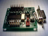
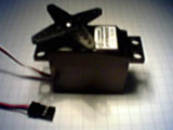
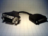
Getting Things ReadyThree hardware hacks were necessary before I could begin constructing the robot. First, the SV203 had to be modified. The SV203 communicates over a serial line using RS232 voltage levels. Palmpilots also use RS232 voltage levels and can be plugged directly into the SV203. The Visor, however, uses TTL voltage levels. Modifying the SV203 to use TTL voltage levels is quite simple. The MAX level-shifting chip that ordinarily shifts the board's natural TTL levels to RS232 before sending signals to the serial port must simply be removed and replaced with two jumpers. This is described in detail on Acroname's website at http://www.acroname.com/robotics/info/PPRK/visor.html. Second, a cable had to be made to connect the SV203 and the Visor. The wiring diagram for this cable is described on Acroname's website at http://www.acroname.com/robotics/info/PPRK/visor.html. Third, the servos had to be modifed for full rotation. Normally a servo rotates about 180 degrees which is no good for a wheel. I have a detailed description of how this was done.
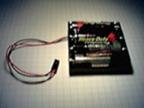
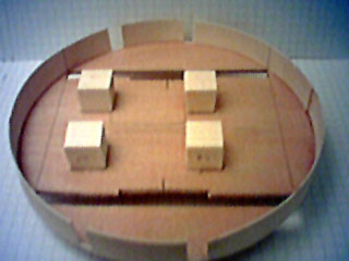
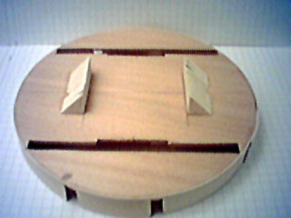
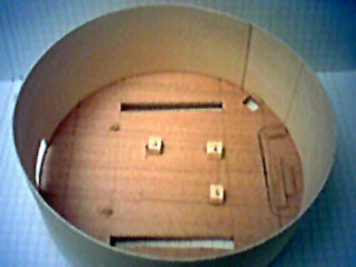
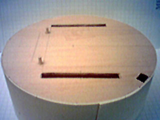
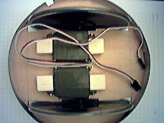
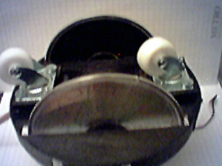
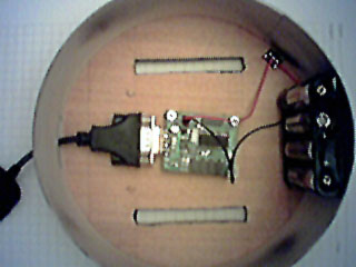
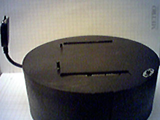
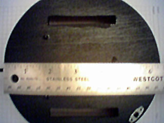
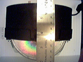
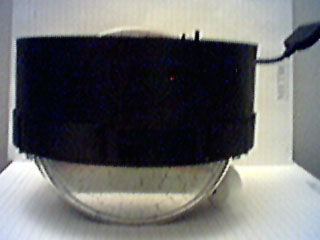
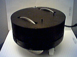
Putting it All TogetherThe design of Visorbot is as follows. I used old discarded CDs as the wheels. They are attached directly to the servo horns. While small wheels would look cooler (and provide more torque), there is a problem. I didn't use ordinary motors, I used servos. Servos have several advantages, mainly a nicely packaged gearbox and the ability to control them from a servo controller board, including on/off, direction, and speed. However, they aren't very fast. The gears bring the main axle speed down quite a bit. Once I modifed the servos for full rotation I measured the rotation rate to be slightly less than one rotation per second. If I round this to one rotation per second then it is easy to find the speed of the robot for a given wheel size. The speed is simply the circumference of the wheel. CDs have a circumference of about fifteen inches, so even with wheels as big as CDs I expect my robot to move only about a foot per second (remember the rotation rate was actually a touch less than one rotation per second). CDs do have the advantage of being very lightweight which is nice. The thin slick edges of the CDs proved to be quite problematic. The had virtually no grip. As a solution to this problem I slit some vinyl tubing and wrapped it around the edge of the CDs, thus providing a thicker rubber surface. This worked quite well for providing traction to the robot. The main body is a wooden box approximately 6.5 inches in diameter and 2.5 inches deep. The wheels won't be mounted on the sides of the box. Instead I cut parallel slits through the top and bottom of the box as far away from each other as possible while still being long enough to enclose the CDs' diameters. The servos are be mounted inside the box with the CDs projecting through the top and bottom of the box. The wheels are front/back centered, one on each side of the box, with small support casters in front and back. The advantage of this diamond layout design over a more conventional square layout is that the robot can rotate in place by rotating the two wheels in opposite directions. Since the wheels are contained within the perimeter of the box, it is possible to place the IR distance sensors at any position around the outside of the box. The SV203 supports up to five A/D inputs, so I could have had up to five IR sensors. However, when this project was completed, I had not added any such sensors. The only sensor available to Visorbot was the color camera. The Visor must sit on top of the box, centered, pointing straight forward, because the Eyemodule camera plugs directly into the front of the Visor and cannot be moved. Additional advantages of having the Visor on top instead of inside the box are that the Visor's relatively large screen can be used to provide data while the robot is running and since the screen is touch-sensative it can be used to send commands to the robot. The SV203 and the battery case are both hidden inside the box with the servos. Thus the robot has a very clean appearance. Here are some pictures of the unpainted box. Note that the top and bottom of the robot are reversed from the top and bottom of the box. I used the lid of the box as the bottom of the robot and the "box" of the box as the main body of the robot. The reasons for this were to make it easier to install the servos and to keep as much wiring as possible in one half of the body.
Here are some pictures of the painted box, internal electronics, measurements, and the whole thing put together.
Programming, Software, BehaviorI successfully interfaced the Visor to the SV203 to control the servos. I never added any IR distance sensors, so there are none, and the corresponding A/D inputs on the SV203 are unused as a result. I was much more interested in the Eyemodule than the IR sensors anyway. The IR sensors would have been used solely for simple object avoidance at first. The Eyemodule provides 320x240 color vision which is a hell of a lot of useful information. While the Eyemodule takes shitty pictures if you're planning on taking it on your next vacation, what it provides to a robot is truly remarkable. There is no way the Visor's fairly weak computer can process the Eyemodule images with the complexity that they deserve. My intention was to run a variety of experiments with the vision system, most of which would have used extremely numb simplifications of the Eyemodule's actual capabilities. Later on, I might have experimented with combining the modalities of vision and IR to achieve increasing qualities of performance in the robot's behavior. I strongly believe in the idea of evolving hardware concurrently with software, so I considered beginning by having the robot simply detect light and dark in the center of the field of view. I would have then increased the available spatial or luminosity resolution of this sensor over time, eventually adding color. If I had built multiple robots of this design, one thing that I find very intriguing is collective robotics. Visors (and all PalmOS devices) have a built-in IR message passing system which I could have taken advantage of for the purpose of robot-to-robot communication. This aspect of this project never happened though. Only the prototype was built. I successfully interfaced with the camera in software and I wrote a basic photovore program. A photovore is attracted to light. In other words I can guide the robot around on by holding a flashlight in front of it. It steers to follow the flashlight. It's a basic and fairly stupid program, but serves as a good testbed for integrating camera images and servo control within a single program. As it turned out, I discontinued work on this project soon after writing the photovore software so I never expanded on Visorbot's behavioral capabilities.
Future Hardware EnhancementsThere are two ways in which this system can easily be enhanced from a hardware perspective. The first and simplest comes from the fact that SV203 can control up to eight servos and my present design only uses two. Possibile expansions of the present system include putting a gripper on the robot with-which to pick up things, putting a telescope on the body that can be swiveled in front of the camera, putting a servo under the Visor so the camera can be rotated side to side, putting another servo under the camera so the camera can also be rotated up and down, plus any number of other ideas such as speakers, buzzers, lights, etc. The second enhancement is that instead of increasing the outputs, I can increase the inputs. The SV203 has only five A/D inputs and I would like almost that many IR distance sensors, so that pretty maxes it out. However, since I am using boolean signals for the IR sensors, I am basically not taking advantage of the fact that the A/D inputs provide an even range of signal between 0 and 255. If I wire the IR sensors so that they overlap on a single A/D input but provide their feedback within different signal ranges, that will free up A/D inputs for other things, like microphones, light-sensors, temperature sensors, touch/bump-sensors, proprioceptive wheel-rotation sensors, tilt-sensors, etc. This overlap would work by breaking up the signal into overlapping but distinguishable regions. For example, one IR sensor could return a 0 or a 128 depending on its boolean state. Another IR sensor could send a 0 or a 64. A third IR sensor would send a 0 or a 32. Ideally, reading these sensor valus would simply look at the bits of the returned signal. Each bit would be personalized to a particular sensor. However, sensors are dirty so that won't work. However, I could look at various ranges of the 0 - 255 signal. If the signal is less than 128, then sensor 1 is off. Otherwise sensor 1 is on. If the signal is between 0 and 64 or between 128 and 192, then sensor 2 ir off. Otherwise sensor 2 is on, and so on down the line. Doing this would require putting resisters in the feedback signal from each sensor that would reduce the voltage from the max (five volts which maps to a signal value of 255) to some power-of-two fraction of that value. It wouldn't be too difficult (at least I don't think so).
AcknowledgmentsI am primarily a software person. While I am fairly adept with simple hardware I'm not too incredibly confident when it comes to designing or building circuits or soldering on expensive circuit boards (I got a little better at this when I started doing astrophotography), which greatly boosted my confidence on such tasks. Several people were extremely helpful, some for offering information, others for actually helping out with some hardware implementation. Kevin Rock was a fellow graduate student at UNM at the time. He hacked the DB9/Visor cable for me (which I probably could have done) and also desoldered the MAX chip off the SV203 and jumped a few connections across the chip's pin connectors on the SV203 (which I probably would have fried the SV203 trying to do). In addition to those two things, he also designed and built custom IR distance sensors for me that cost a fraction of the commercial devices (which I ultimately never used in this project). He was building his own robot which would kick my robot's ass, but he's more of an Electrical Engineering type while I feel more comfortable in the depths of computer code. I'm much more interested in robotic behavior myself.
Robert Van Deest runs a cool website describing projects with the SV203 in addition to several other devices. He describes interfacing Palmpilots with the SV203 (which is much easier than the Visor) and is very interested in expanding his website to include SV203/Visor communication.
Jacob Christ works at (owns? runs?) Pontech. When I needed an SV203 that was modified for the Visor he offered to perform that hardware hack for me before sending the SV203 to me. In the end I didn't go this route (instead Kevin Rock did the hack for me), but he offered to do this at no expense and I really appreciate his generosity. |
||||||||||||||||||||||||||||||||||||||||||