|
|
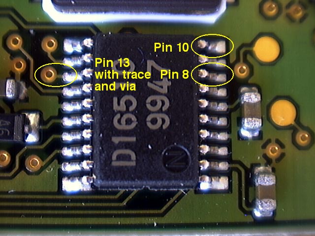 |
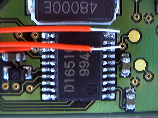
A closeup of the 16510 chip. The pins are numbered counter-clockwise starting with pin 1 at the lower right.
Click to enlarge.
|
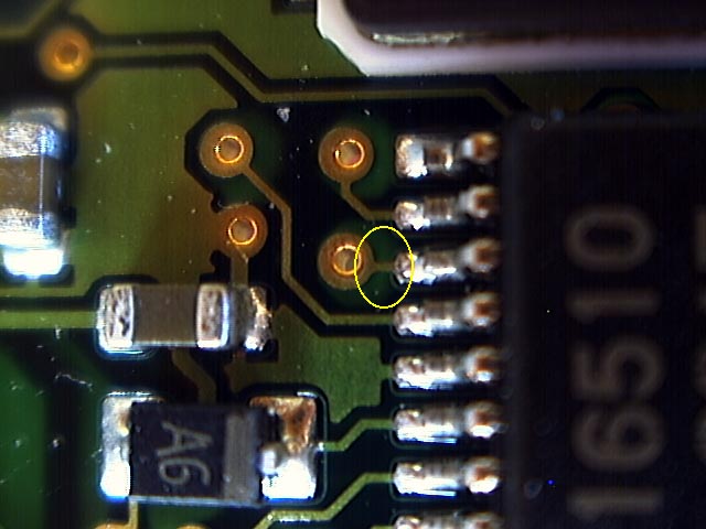 |
The trace at pin 13.
Click to enlarge.
|
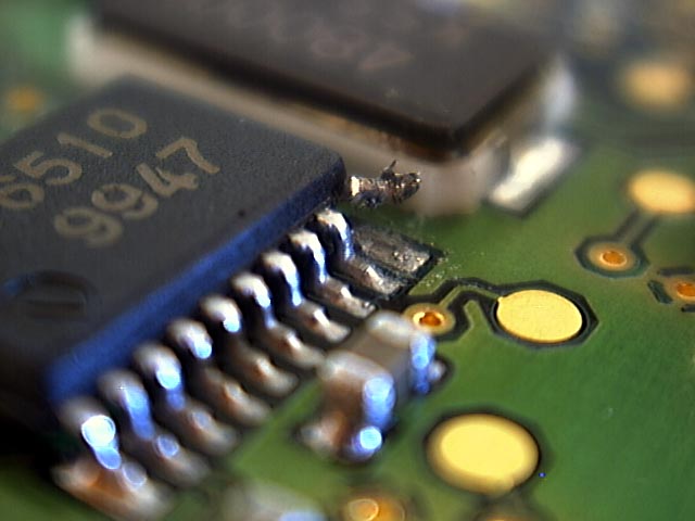 |
I lifted pin 10 by slowly wedging an x-acto blade under the pin until it broke free from the pad and then carefully bending it up. It is very very delicate. Be careful. If it breaks off you're going to have a really bad day.
Click to enlarge.
|
 |
In this image I have cut through the trace at pin 13. Be careful here too. It's precision work. I tested it with the continuity function on a multimeter to make sure the trace was fully severed.
Click to enlarge.
|
 |
Three wires must be soldered to the board, one to the lifted pin 10, one to pin 8 (or pin 13 would work just as well), and one through the via at pin 13. To fix the wires down while I solder them I glued them to the board at a distance from the 16510.
Click to enlarge.
|
 |
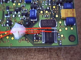
Here are the wires held down at the 16510 prior to soldering.
Click to enlarge.
|
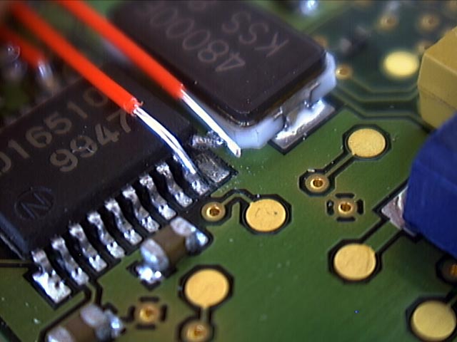 |
I bent the wire at pin 8 over so that it carefully aligned with the pin. This would aid soldering.
Click to enlarge.
|
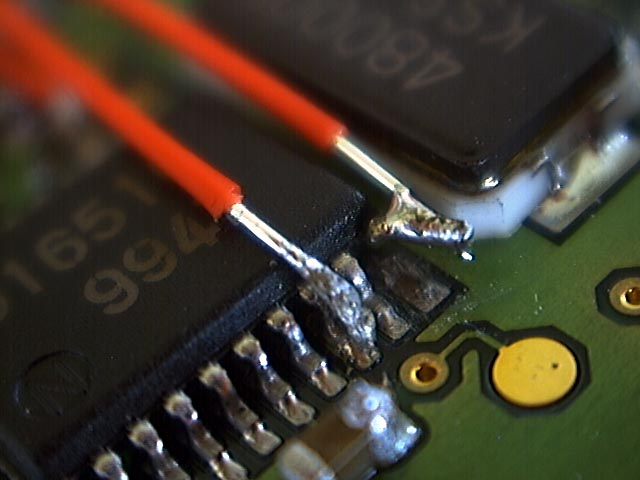 |
Pin 8 and 10 are soldered in this image. To solder pin 8 prepare the wire in advance by dousing it in solder. Then to solder it, bend it over the pin and touch it with the soldering iron. The solder will instantly bond to the pin. Be ultracareful to avoid a solder bridge to the neighboring pins. It would be very difficult to repair. Test all the solder bonds with the contuity function on a multimeter.
Click to enlarge.
|
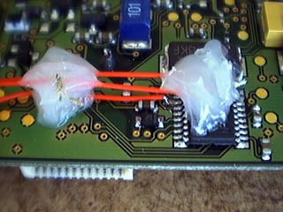 |
After soldering this side of the board I fixed the two wires over the 16510 down with glue so they would break off.
Click to enlarge.
|
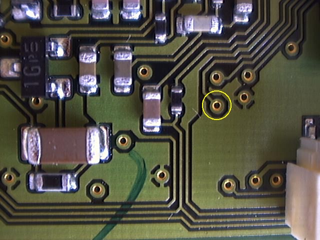 |
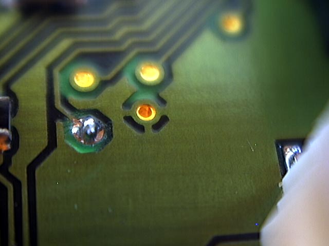
This is the neighborhood of the via at pin 13 on the other side of the board.
Click to enlarge.
|
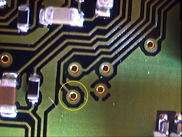 |
Here's a closeup.
Click to enlarge.
|
 |
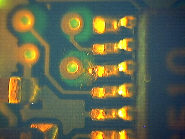
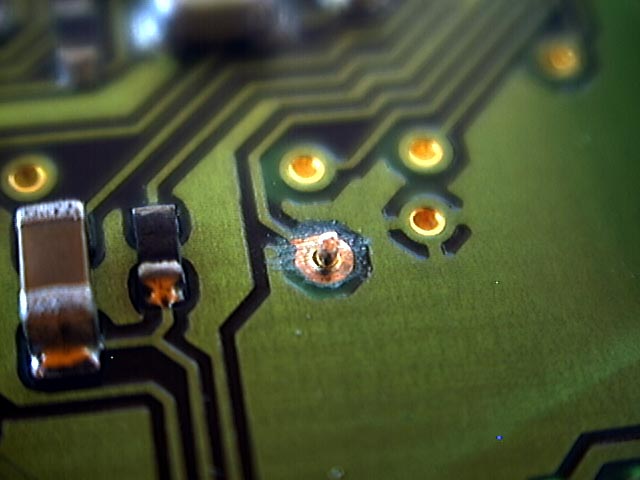
It is important to scrape the covering off the via to expose the raw copper so you can solder to it. Be gentle.
Click to enlarge.
|
 |
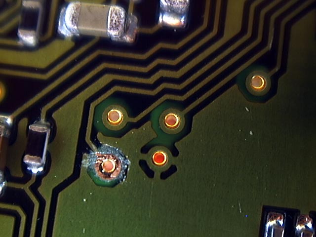
The wire protrudes through the via from the other side of the board...
Click to enlarge.
|
 |
...and is soldered in place.
Click to enlarge.
|
