Mayan Forest Simulation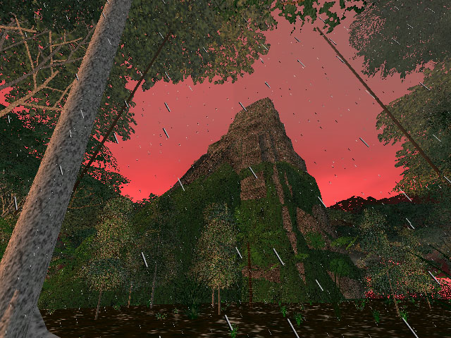
Sections:

History of the ProjectThis is one of the most ambitious projects I have ever undertaken. There were two primary goals. The first was to create a 3D environment that would recreate the sense of wonder and awe I feel when I find myself in a tropical rainforest. The second was to create a realtime 3D game in which the player explores a lush, detailed, rich Central American rainforest populated with numerous plant and animal species, in addition to numerous Mayan ruins in various states of reclamation by the forest. The game would have been first-person and puzzle-oriented, not action-oriented, where the user would find and explore pyramids and other ruined buildings in the forest, figuring out how to use ancient machines and deciphering codes based on Mayan hieroglyphics and the Mayan calendars (yes, there's more than one). I envisioned a game-design that represented a union of Myst type puzzle-solving and exploration with an Indiana Jones or Tombraider focus on rainforest based civilizations and the ruins of their cities, although it wouldn't feel like most games in the Myst series because they are not fluid 3D worlds (with the exception of realMyst). Actually, realMyst is pretty close to what I had in mind, except placed in a Mayan rainforest, focused on overgrown pyramids and other ruins, and with my own personal flavor of puzzles to solve. I slaved over this project for about a year, and in the end it kind of fizzled. The problem was not with any aspect of the 3D environment, which turned out to be really beautiful, but in the design of the puzzles and the story, and in a lack of interesting gameplay. I had trouble designing a good game and devising good puzzles. This left me with a fantastic sophisticated 3D simulation of a rainforest that had no purpose. It's really too bad. This webpage describes the various aspects of the simulation, with only minor comments on the game-oriented features, since they ended up being so incomplete and unimpressive relative to the rest of the simulation. This project was built using Quesa and building on the Queeg example included with the Quesa package. This approach, Quesa as the underlying 3D powerhouse, and Queeg as the extended object-oriented world-management system, is how I have constructed most (but not all) of my 3D applications to date, including Vertigo and 3D Multiple Robot Simulator. Plant and pyramid models were constructed in Meshwork. I relied very heavily on the publically available Nanosaur I code to help me figure out how to get a complex QD3D world going (Quesa is simply a reimplementation of the QD3D API, so lessons from one translate almost seemlessly to the other). Project DiaryI had the fortune of great foresight when I started this project in that I knew in advance that this would be a large, long-term software-design and implementation-heavy venture. As a result, I struck on the idea of keeping a diary from almost the very first moments I conceived the project. The purpose of the diary was that after I completed the game, released it, made tons of money, and became famous, people might like to read my project-diary to muse on and learn from my experience. Although most (okay, none) of those hopes panned out, the diary is nevertheless fascinating (and long), and I offer it here for your reading pleasure.
World-building Tools, External ProgramsIn order to create the main simulation program, I wrote a number of small helper programs on the side that served as world-building tools. These programs read input files for various data (texture palettes, cell-texture assignments, terrain extrusion height-maps, object-placements, and water placements), and process them into a format that is efficient for the simulation to read directly when the simulation is launched. The following is a list and description of the helper applications. Texture ConverterThe TextureConverter converts a palette of 32 bit cell-textures (a cell is a 1 meter square area of terrain) into a palette of 16 bit square pow-2 textures that are formatted properly for the simulation. The program is hardcoded to use an input file named "texture.raw" which starts with an unsigned short for the number of textures and an unsigned short for the texture width and height in pixels (must be pow-2). The input file must store 32 bit textures and must be arranged vertically, one cell wide and n cells tall for a palette with n textures. The advantage of a vertical layout is that the raw byte order of the file does not interlace the rows of the individual textures. This makes it easy to scan one texture at a time from the file. The program is hardcorded to produce an output file named "texture.ter". The texture.ter file will not be used by any other setup programs. It will be read directly by the simulation. The simulation presently downsamples the textures when they are read into a series of mipmap-like textures, such that lower-resolution textures are rendered for cells that are distant from the player's location. Basically, this program just converts a 32 bit texture palette to a 16 bit texture palette, making sure the number of textures and the texture dimensions are appended in the first pair of shorts of the file (the first four bytes). This could easily be done in Photoshop of course, saving as a 16 bit raw image file, and using a hex editor afterwards to manually insert the first four bytes of data. The reason for this program's existence is that it originally automatically downsampled the textures at many resolutions (ala mipmaps) and stored all the downsampled versions of each texture in the output file. This is antiquated however, since the simulation itself performs the downsampling as the texture palette is read at launch time. Thus, this program is kind of pointless in its present incarnation. The simulation cannot support more than 256 cell-textures (the reason for this is explained in the section on the Terrain Texture Converter). Terrain Texture ConverterThe TerrainTextureConverter creates a cell-texture assignment map for the entire world. In other words, it assigns a texture to each cell in the world working from a palette of textures. It is assumed that the world is square and pow-2 in dimension (where the unit is cells, or 1-meter squares of terrain). The simulation can have up to 256 unique cell-textures. The output file is hardcoded to be named "terrainTexture.ter" and is not used by any other setup programs. It will be read directly by the simulation. The input file uses a one byte index to represent the texture assignment for each cell, thus the 256 limit on the number of cell-textures that are possible. The input file is basically an 8 bit grayscale image, most easily generated in a program like Photoshop. It is important that the cell-texture assignment legally match the cell-texture palette, in that the palette must contain enough textures to provide for the highest indexed assignment in the texture assignment map. Is it loosely assumed that the texture assignment map is "compacted downward", meaning that if m is the highest index in the assignment map, then every index in the range 0 to m is present somewhere in the assignment map. It might appear at first that this program simply regurgitates the input grayscale texture-assignment into an identical output file, but this program also divides the world up into tiles. The input image uses one pixel to represent one square meter of the world, or one cell. However, it has no notion of tiles. Tiles are square blocks of cells. I used 32 cells across and down as the size of my tiles, for reasons that are explained in the Terrain Engine section below. The output of the TerrainTextureConverter groups the cell-texture-assignments by tile, so that all of the cell-texture assignments for the first tile occur in a row in the output file, followed by the second tile and so on. This is not the case of the input file, which, given its arrangement, effectively interlaces the tiles row by row. The simulation will require the tile-by-tile arrangement and that reorganization of the cell-texture assignments is the primary purpose of this program. Note that the function of this program has since been wrapped into TerrainExtrusionConverter2, described below, which permits "painting" of the terrain with cell-texture assignment brushes. Thus, this program is basically obsolete now.
Texture Extrusion ConverterThe TerrainExtrusionConverter has evolved considerably since its inception. Originally it only had the job of taking a grayscale extrusion map and creating a terrain trimesh file for the simulation. A trimesh is a geometric 3D model that only has triangular faces. Trimeshes can be rendered must more quickly than models with arbitrarily shaped faces. Examples of trimeshes for a single tile are shown in Figure 4. This included creating trimeshes at various resolutions in advance so the simulation would not have to calculate the downsampled trimeshes at load time. Over time, this program has grown into the object-placement, water-placement, and cell-texture assignemnt interface for world-building as well. It has basically assumed all world-building tasks except the 32 bit to 16 conversion performed by the TextureConverter program, mentioned above. When launched this program will automatically attempt to open several input files with hardcoded file names:
If any of these files are not found, it is assumed that a blank is desired by the user, and the associated data structures are initialized to empty states. For example, to take a presently existing extrusion map and reassign new object placments to it, the user would retain the "te" file but trash, move, or rename the "op" file before launching TerrainExtrusionConverter. The input extrusion map file is a 16 bit grayscale height map, most easily made in a program like Photoshop, marking the ground height for all locations in the world at a 1-meter spacing (the corners of 1 meter cells, as defined above). The user can explicitly create trimeshes at a variety of resolutions and then save them to trimesh files that will be used by the simulation. It is necessary for the user to create all the trimesh levels in this manner (there are eight, numbered 0 through 7). In a future, more automated, version of the program all the trimesh levels would be created with a single user command but this is not important. 
Figure 3: The main window in TerrainExtrusionConverter. The grayscale extrusion map is shown in both halves, although it is heavily obscured in the right half. The left half shown the placement of water objects. Water objects are trapezoidal. They can be tilted around their symmetric axis and during the simulation a water texture will be uv-animated along the asymmetric axis in the direction shown in the figure (water flows toward the dots on the cyan line segments).
The trimeshes, regardless of resolution, are automatically optimized by using large triangles in flat areas and small triangles in areas of decidedly important height change. The sensitivity to a minimum scale of height change corresponds to trimeshes at various "resolutions". The optimization algorithm uses "crucial" points which are deemed important enough to be required for the resolution in question, and "noncrucial" points, which are also read from the height map but which are not important themselves, only as "support struts" for the trimesh to properly triangulate the crucial points. In the program, crucial points are drawn in cyan and noncrucial points are drawn in yellow in the Tile TriMesh window. 
Figure 4: Eight possible views of the Tile Trimesh window for the hilited tile in Figure 3. Only one window exists the program and it will show the trimesh corresponding to resolution the user has most recently created (through a menu command). Tiles optimized to use large triangles in flat areas and small triangles in vertical or bumpy areas. The sensitivity to height changes dictates the resolution of a particular trimesh. Note that some points are required due to the sensitivity, i.e., they are "crucial" (shown in cyan) and some merely define "support struts" that are necessary to properly triangulate the crucial points (noncrucial support points are shown in yellow). Only tiles within a specified horizon of the user will be submitted to the renderer in each rendering cycle (this is described in greater detail in the Terrain Engine section below). In addition, notice that the TerrainExtrusionConverter program generates eight trimeshes of varying resolution for every tile. If a tile is to be submitted because it is within the submission horizon of the user, the decision about what resolution trimesh should be submitted for that tile is also decided based on the tile's distance from the user, favoring high resolution for tiles nearer to the user's location. The TerrainExtrusionConverter is also the interface for water placement, object placement, and cell-texture painting as well. At the present time, the only kinds of objects are plants that are used to populate a rainforest type world, and a few pyramids and ruins. The program reads in a file that contains a table of all the object types that can be placed in the world. This table lists each type on a row, with each row in the following format: numModels | modelNameN | modelRigiditiesN | maxVisibleDistN | collisionRadiusN | verticalSupport | maxRepeat | repeatXYZ | locationOffsetMinXYZ | locationOffsetMaxXYZ | maxRotation | maxScaler | minObjectSpacingMN | maxObjectSpacingMN where the tags are:
Some of the parameters listed effect where and how objects are placed in the world while others effect how objects behave during the simulation. These parameters is discussed in greater detail in the later section, Object Engine. Objects can be placed individually by clicking in the Tile Objects window. The object type that is placed is randomly chosen from a boolean mask of all of the object types. In order to place a specific object type, the user disables the mask for all types except the desired type. An object's orientiation is shown with a radial line marking its forward vector. To delete an object, option-click on the object's circular boundary. Objects can also be randomly "peppered" or splattered into the world, either in a single tile or in the entire world. The Tile menu has these commands. The palette of available object types for splattering can be masked to any subcombination of the full type list. The mask is altered by clicking on the object type names in the Random Object Type Mask window (not shown). The object placement can be saved to a file hardcoded to the name "op" and then renamed for the simulation. This file will be read directly by the simulation or when TerrainExtrusionConverter is relaunched. Water placement is the process by which panes of animated flowing water are added to the world. I used these kinds of objects to create a creek or sorts. Each water pane is a trapezoid (which allows the water to follow a curved path, as shown in Figure 3) and can be tilted up or down around its symmetric axis (orthogonal to the opposing and parallel edges of the trapezoid) to allow water to flow down a steep grade (or a waterfall). The water objects are shown in the left half of Figure 3, with the cyan segments denoting the direction of water flow (water flows toward the dot on the segments). Cell-texture assignment is handled by TerrainExtrusionConverter as well, which makes TerrainTextureConverter, mentioned above, relatively obsolete. Cell-texture assignment is accomplished by enabling cell-textures on a palette mask (similar to enabling the object type mask for object creation) and painting them onto the Tile Objects window, shown in Figure 5. In order to mix textures up, to achieve a nice blending effect, the texture palette represents a mask, where any texture that is enabled may be chosen at random as the assignment for the cell presently under the paint brush. By having multiple textures of similar appearance that represent a given type of ground, a nice blending effect can be achieved and ugly teselating patterns can be avoided. This could also be achieved by randomly rotating and flipping a texture as it is assigned to a cell, but I didn't bother implementing such a feature.
The Terrain EngineThe terrain engine is by far the most sophisticated component of the simulation. I spent many months working on the terrain engine before ever considering populating the world with plants, weather, pyramids, or anything else. In fact, I continued to experiment with various approaches to terrain management throughout the project. Proper handling of the terrain, by which I mean the extruded ground beneath the user, is extremely complicated in two ways, both arising from its expansive size. The terrain, after all, is effectively one gigantic 3D object, an extruded bumpy surface that resides under the user's feet throughout the entire world. Let me preface a discussion of terrain by admitting the limitations of an extrusion-based model. Since extruded terrain can only push and pull an intial sheet vertically at various points, and since the sheet can neither fold, wrap, or be punctured, extruded terrain represents an extremely limited form of terrain. Caves, overhangs, and holes throught the terrain into the area beneath the terrain are completely impossible with basic extruded terrain. Likewise, my simulation uses nondynamic terrain. The terrain cannot be altered in shape during the simulation. This is not particularly important, but does represent a further limitation of the terrain engine which might be detrimental to certain types of applications. I contemplated extending the terrain engine to a more versatile mode, but never bothered taking the leap. Nevertheless, the topic fascsinates me. The large size of the terrain causes two problems. The first is the large number of vertices required to represent the terrain extrusion with sufficient detail. A one kilometer square world with a resolution of one meter would have 1,002,001 vertices, 3,002,000 edges, and 2,000,000 triangles. Additionally, a large terrain is represented by a truly unimaginably large texture. One could assume a simple, basic texture that tiles repeatedly throughout the world, but if the world must have unique locations with different kinds of texture, say dirt vs grass vs sand, then a unique texture must cover the entire world. At a resolution of 32 pixels per meter (my cell-textures are 32x32 and represent a cell of one meter in size), a square kilometer terrain's entire texture is 32,000 pixels wide and tall, or a little over one billion pixels. At 16 bits per pixel, that's about two gigs of texture, just for the terrain. My computer has 64 megs of VRAM, and that doesn't take into account whatever extra VRAM is required for nonterrain textures, such as tree bark, tree leaves, water, clouds, etc. The obvious solution is to break the terrain up into tiles and only render certain tiles, based on their locality to the user's location at any given moment. However, there are a number of complex issues that arise. First, a tile size must be chosen. Small tiles have the main advantage that the tile footprint surrounding the user that is rendered more closely represents a circle. This is nice because less terrain geometry will lie beyond the horizon and still have to be rendered because part of the tile's geometry lies inside the horizon. However, small tiles mean more total tiles rendered, and the more objects rendered at a time, the slower the rendering even if the geometric complexity is identical. In other words, imagine two worlds of identical geometric complexity. In the first world no objects are geometrically unioned into single larger objects, but in the second world this is done liberally. Despite their geometric equality, the first world will render slower than the second world. So, we don't want too many tiles because this will slow down the renderer. Additionally, tiling is not sufficient to bring the total geometric complexity of the subset of the terrain that is rendered down enough to speed up rendering enough for a realtime program, unless the horizon is so close that the user can actually see it because it just a few tens of meters away. Bear in mind, that this is all contingent on my design of an extrusion resolution of one point per meter. Thus, I hit on the idea of using high complexity tiles in the near ground and low complexity tiles in the far ground. This was described briefly in the previous section on the TerrainExtrusionConverter program. For each tile, I generate the corresponding extrusion geometry at eight levels of resolution, and I submit the one level for each rendered tile that results from its distance from the user. Figure 6 illustrates this. 
Figure 6: Varying tile resolution. Each tile is represented by one of eight different trimeshes of varying detail. For tiles near the user, high resolution trimeshes are rendered. For tiles far from the user, low resolution trimeshes are rendered. In this figure, the user is located near the fork in the creek, which is slightly below the center of the image. You can plainly see that the geometric detail is richer in that area and fades out in the distance.
The terrain texture caused similar problems. First of all, I couldn't store the texture for each tile in advance as an input file. It would have taken up too much harddrive and RAM space (the 2 gigs mentioned above, assuming a one kilometer world at 32 texture pixels per meter). So I quilt the cell-textures together for each tile at runtime. Similarly, I found it necessary to use smaller textures (lower res textures) for tiles in the distance. This has two benefits. The first is that the renderer is less heavily loaded and renders faster, the second is that this saves VRAM. Using a series of resolutions for textures is called mipmapping, but rather than let the 3D graphics library do it for me automatically, I chose to manage this directly within the simulation. I mipmap at as many resolutions as the original texture size allows. Since I used textures of 32x32, I created lower res textures of resolution 16, 8, 4, 2, and 1. To help you visualiize the effect, when rendering a really far away tile that is barely within the rendering horizon, I draw a texture on that tile that uses a single pixel to represent a square meter of ground. That is not the end of the terrain engine however. More needs to be done. First of all, any 3D system that uses lighting needs to know the normal vectors for the vertices and/or faces in the system. However, calculating the vertex normals for the terrain is rather expensive and takes a long time. Thus, to speed things up, I generate the vertex normals once, the first time the simulation is run with a brand new extrusion map, and save the vertex normals to a file. On subsequent launches of the simulation, it attempts to find a vertex normal file and read it in quickly instead of regenerating the vertex normals. Thus, if I create a new extruded terrain map, it is crucial to rename, move, or destroy the vertex normal file before I run the simulation the first time with the new terrain. Incidently, this notion of lazy evaluation of vertex normals is extended through the terrain engine in many ways. There are numerous places in the terrain engine where I do not construct various data structures until they are needed as a result of the user wandering into a particular area of the world. Rendering is still too slow if all of the calculations described above (construction of trimeshes and quilted texturs at numerous resolutions for every tile) are performed at launch time however. Rendering is okay, but launching the simulation takes forever. Thus, I adopted a lazy evaluation strategy, whereby a tile's terrain geometry not generated until the user wanders into its range, and then, only the geometry resolution that is required at any given moment is generated, not all eight resolutions at once). Likewise, a tile's quilted texture map is only generated when needed, and again, only at the resolution needed. Once the terrain geometry and texture are created, they are cached so they won't have to be created again if the user wanders away from and then returns to a tile. There was some concern that the RAM requirements may grow to an unacceptable amount as the user fully explores the whole world, but this did not turn out to be a major problem. I also experimented with unioning tiles into larger union-tiles. This would have the benefit of reducing the number of objects submitted to the renderer. However, since tiles are rendered with varying geometric resolutions, they are always changing, from the renderer's point of view. Thus, it proved to be almost pointless to union tiles and in the end I turned the feature off without noticing much difference in performance. One final problem I faced was simply generating in RAM and paging huge terrain textures into VRAM fast enough. When the user came within the closest possible range of a tile such that the tile needed the highest resolution texture possible, the texture for that tile would be just over two megs: 32 pixels per cell/meter * 32 cells per tile, squared, times 2 for 16 bits per pixel = 2,097,152 bytes. Thus, when the user closely approached a tile for the first time, the simulation would hiccup badly. If the user wandered away and came back to that tile, there would be no hiccup and the beautiful high-res terrain texture would appear smoothly. Thus, either the lazy creation of the terrain texture, or the paging of the texture into VRAM was causing this problem. It was difficult to tell which, and I didn't bother with it too much. Instead, I simply truncated the terrain resolution at the second highest resolution, 16 pixels per meter. It's too bad, but that's what I resorted to.
The Object EngineIn the TerrainExtrusionConverter section, I described how the world-building tool is used to place objects in the world. To summarize, there is a library of plant species which correspond to 3D models I constructed in Meshwork. Each type has a set of parameters that govern both how the object is placed in the world in TerrainExtrusionConverter and how the object behaves in the simulation. These traits were listed above. Part of the object engine is the sophisticated manner in which objects are placed in the world by TerrainExtrusionConverter. The parameters listed above that effect placement are maxRepeatN, repeatXYZ, locationOffsetMinXYZ, and locationOffsetMaxXYZ. maxRepeatN defines the maximum number of times that an object can be duplicated with translation when it is created. I used this to create philodendrans of varying height. repeatXYZ is three parameters that govern how repeated copies as translated. In the case of philodendrans, the copies were translated vertically by the height of the philodendran model (Figure 7). 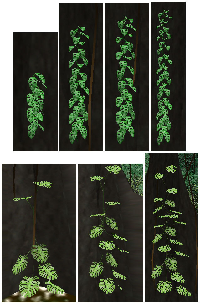
Figure 7: TerrainExtrusionConverter used duplication parameters (maxRepeatN and repeatXYZ) to allow an object to be placed multiple times with an associated translation during the object's creation. I did this specifically to allow a greater variety in the appearance of philodendrans, as shown in this figure. Finding ways to increase the diversity of the simulated rainforest was an overarching theme of this project. Also note that philodendrans and vertical vines are always placed right next to thick tree trunks and in the case of philodendrans (but not vertical vines) are always oriented facing away from the tree trunk. These placements are controlled by the minObjectSpacingAB, maxObjectSpacingAB, and maxRotation parameters, which force philodendrans and vines to be placed somewhere on the boundary of a circle at a particular distance from the center of each major tree species, depending on that tree species' trunk girth, and from a low maxRotation (in the case of philodendrans but not vines) parameter such that they take on the orientation of their displacement from the tree trunk's location and then are not rotated very much afterwards. The locationOffsetMinXYZ and locationOffsetMaxXYZ parameters effect how an object can be translated in its initial placement, as opposed to its possible repeated placements, as mentioned above. This feature was used mainly to allow palm trees to be easily created with varying height trunks and to allow vertical lianas (vines) to be suspended at varying heights above the ground. The palm trees had a location offset range that was negative, allowing them to be placed slightly below the present ground level, which created the appearance of a shorter trunk. The vines had an offset range that was positive, so they could be suspended above the ground. 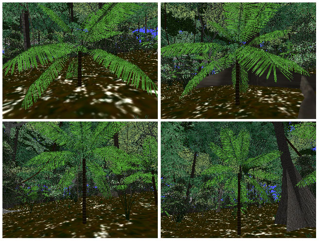
Figure 8: TerrainExtrusionConverter has parameters that allow an object's placement to be offset (locationOffsetMinXYZ and locationOffsetMaxXYZ). In the case of palm trees, I used this to lower the tree by a random amount into the ground. Thus, I could achieve the effect of plam trees with a variety of trunk heights with a single 3D palm tree model. Despite the sophistication of the object placement routines in the world-building stage, there is quite a bit of complex behavior that objects exhibit during the simulation as well. One of the most important features I ever added to the simulation was permitting the plants to sway lazily in the breeze. This serves two functions. The first is that it lends the simulation a deep verisimilitude that a static world lacks. When the plants don't move, the world appears dead and uninteresting. When the plants start swaying, ever so slightly, the world suddenly comes alive. A similar effect has commonly been observed by researchers of "talking heads", 3D modeled heads that converse as chat-bots with a user, ala the Turing test. When these heads are allowed to move around slightly, they seem much more alive. A similar effect is seen in many video games. Halo, for example, shows each kind of creature moving slightly, even when it is standing still. The second advantage of having the plants sway is that this allows the user to much more easily discern individual plants in the foreground from the visual clutter of the background. Without stereoscopic vision (which I did not bother to render in this project), the scene immediately blends into a hodgepodge of mixed color when the user stops moving through the forest. This problem is present in the various screenshots shown on this webpage for example. Plant swaying helps alleviate this problem. Plant swaying is accomplished by letting each plant (actually, each model within each plant, notice that some plants have multiple models, such as one for the trunk and one for the leaves) to oscillate sinusoidally on both the X and Z axes. Thus, they oscillate in an ellipse. The motion is not translative in that the plants don't slide around in an ellipse, which would of course look very unnatural. Instead, they rotate elliptically around their roots. The higher and taller a plant is, the more severe the oscillation is allowed to be, as governed by the modelRigiditiesN parameter, listed above. So, trunks can't sway very much, but canopies can sway quite a bit. Complex plant models cause the same problems for the renderer that the terrain does. Having thousands of complex plants in the world, each with both complex vertex geometry and large textures, is quite wasteful. Thus, a significant amount of optimization is performed. First, all plants of the same species refer to the same texture in VRAM. This is only logical as otherwise the same texture would be repeated wastefully in VRAM. Second, each plant species is represented by multiple geometric models and multiple texture resolutions, exactly as done with terrain, as described above. Plants that are far away are rendered using simpler geometric models and smaller textures. Third, in tiles that are relatively distant from the user, all plants of a particular species are unioned into a single geometric object, thus reducing the number of objects submitted to the renderer. This unioning precludes the swaying effect however, so it cannot be applied to tiles that are immediately near the user. Fourth, each plant species has a parameter that governs its rendering horizon, much like terrain tiles. This parameter is maxVisibleDistN in the list above. Small, low-lieing plants, like grass, have a fairly short horizon and are eliminated from rendering with a quick dropoff in distance from the user. Large plants like canopy trees have a very far horizon. Medium plants like short trees and bushes have a medium horizon. Collision detection is very minimal in the simulation. Most large plants have a collision radius that prevents the user from walking straight through them, pushing the user around them if possible. Sometimes the user gets stuck in the root structure of a large buttress tree and can't push his way through (get pushed around automatically), and has to back up or turn around to avoid the tree. All object types have a boolean that defines whether they provide vertical support for the user. The terrain does this of course. No plant species do this, but the various pyramids had to do this in order to enable the user to climb their exterior and descend and otherwise explore their inner chambers. This was fairly easy to do. Given the user's present X, Y, and Z location, I would project a ray downwards and find the first face intersected by the ray that belonged to an object providing vertical support (or the terrain if no object in the user's vicinity provided a face beneath the user). Then I would simply call the discovered intersection's height the ground height and the user would fall or rise to that height as appropriate. This easily enabled me to let the user walk around at various levels within a pyramid, including in rooms that were located above and below one another. To prevent "sticking" when the user hit an object, the user would slide along the intersecting surface and gently rotate away from the obstructing surface. Likewise, falling and climbing were easily accomplished by finding the ground height at the user's location, as described above. In this way, the user could easily run around the forest and the pyramids with minimal distraction from object collisions, while simultaneously providing enough collision detection to give the world some substance from the user's perspective. Water animation is easy to accomplish. The water objects created in TerrainExtrusionConverter correspond to trapezoidal surfaces in the world. I simply apply a water texture to such a trapezoidal surface and then animate the uv coordinates accordingly.
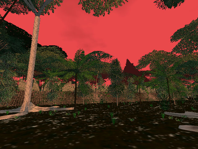
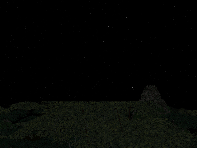
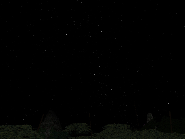
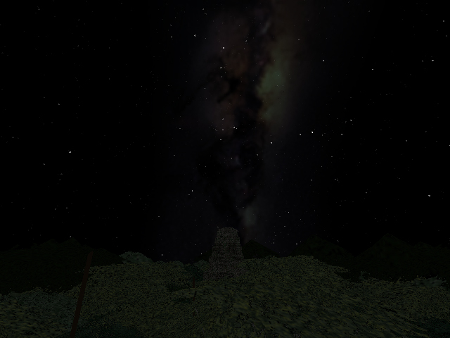
The Day Cycle and Weather EnginesIn addition to the actual forest matter (trees and what not) I decided that I needed a vivid environment in which to place the entire forest. I added a sun disk that orbited the entire world (yep, Galileo was wrong after all), and a directional light source whose direction was correlated with the position of the sun. Realtime renderers (at least Quesa) do not provide real shadows. This effect must be accomplished by an illusion, a second object that looks shadow-like that is rendered in the world in a particular orientation. I dispensed with shadows entirely as a result. However, based on the present time of day (which ran, arbitrarily, at about two real minutes per twenty-four simulated hours. Many games, such as realMyst, use sped up time and increased user-travel speeds) I modulate the light intensity and the light color (dark and orange or purple for sunset and sunrise). After dusk, the light is nearly turned off and the sky goes black. At night I enable a highly realistic star model using a real star catalog containing the 9081 brightest stars in the sky. Stars are represented by a single triangle of nearly single pixel proportions. The catalog is sorted by descending brightness so I can control a single parameter in the simulation to govern how many stars should be rendered by simply controlling how far through the star catalog to read when creating the stars. A short cutoff reads only the brightest star in the catalog. Each star's actual magnitude is lumped into one of five discrete brightnesses. The brightness is then used to determine the star's single triangle's color (a shade of gray such that white is for bright stars and dark gray is for dim stars). Additionally, the five brightness levels correspond to slightly changes in the size of the triangle, so bright stars get slightly larger triangles. Since the original simulation is modeled on a Mayan ruin site, I chose one my personal favorite sites, Tikal, as the latitude and used this to set an inclination to the axis of rotation of the stars around the sky. Lastly, I added a Milky Way model to the simulation. I found a beautiful photograph of the Milky Way online (the photographer never answered my email requesting permission to use the image, but since I never publically released this project, it doesn't really matter anyway) and texture-mapped it on an uncapped, short cylinder (the same basic shape as a flat rubberband). This object is of course placed in the world with the proper orientation such that it aligns correctly with the stars. To buy a little extra rendering power for the many thousands of stars, I decrease the terrain and object rendering thresholds as night begins, on the logical argument that when it is dark, you can't see as far. This works quite well. Truthfully, I am extremely proud of the night-sky model in the simulation. I have been tempted to use it as the starting point of a completely separate project, a night-sky viewer, which might be usefulness to astronomers. The simulation also has a number of very nice weather effects. There are three cloud layers. Clouds are not volumetric or procedural or anything like that. They are flat planes that float above the forest on which I perform uv animation of various tiled cloud textures, generated in Photoshop. I tried photographing actual clouds, but I decided Photoshop clouds looked better. Go figure. The highest layer represents very high cirrus clouds, the middle layer represents low cirrus clouds, somewhat above the canopy. The lowest layer is inside the forest, well beneath the canopy and does an excellent job of showing mist, fog, and small clouds drifting through the forest between the trees. It looks great. Each cloud layer has an associated X and Z axis uv animation speed, such that I can have each cloud layer "blowing" in its own direction at its own speed, distinct from the other two cloud layers. Likewise, I can turn each cloud layer on and off independently, depending on the present weather. What good is a rainforest without rain? I represent rain with vertical planes that float directly in front of the user's view. I use multiple such planes, one right in front of the user, and others a few meters or further in front of the user. The planes have a uv animated texture map of rain (basically short white line segments). I have multiple possible textures with various densities of rain (densities of the line segments) which can be used to represent varying degrees of rain intensity. Likewise, by simply rotating the rain planes around the Z axis I can create the illusion of rain falling diagonally. As the user turns around, the rain planes are rotated in a sin function with respect to the user's Y axis orientation and the present wind direction. As a result, the user visually experiences very natural rain. Looking upwind or downwind yields rain that appears to fall straight down. Rotating left or right increases the diagonal of the rain until ninety degrees across the wind is reached, at which the diagonal of the rain is maximized at some arbitrary angle. Continuing to rotate brings the diagonal aspect of the rain back to vertical. As rain intensity increases, I also decrease the "fog" distance, which is a parameter of the 3D renderer. This greatly aids the illusion of rainfall. One feature that I would like to briefly comment on is the leaf-shadow-light model, as I generally call it. This is an alpha-textured pattern of speckled light projecting through the canopy onto the forest floor that I render just above the terrain and sway elliptically in a pattern similar to the canopy swaying mentioned above, except that the animation in this case is uv animation instead of elliptical model rotation as in the case of the plants. This is a fantastic effect that gives the forest a peaceful sense of motion and an emotional mysteriousness. Unfortunately, a number of people I have shown the simulation to have not understand this model at all. They are entirely confused as to why there are white speckles drifting around on the ground. I find this perplexing and wonder if the people in question has simply never been in a dense forest in their entire lives, because honestly, I think the effect is pretty darn impressive. At any rate, I just wanted to point it out. It's pretty darn cool. Incidentally, since it is a 32 bit alpha-channel texture, it produces a noticable rendering cost.
The Pyramid and Ruin EnginesAlthough I had high aspirations for the "gaminess" of the project, it never really panned out. I spent quite a long time working on the pyramid models. The actual pyramids themselves were not necessarily particular difficult to create. In fact, in some respects they were easier than the plants because I didn't need any code to handle swaying. The pyramids are literally rock-solid. The complexity arose in my attempts to design and encode complex puzzles and articulate machinary into the pyramids for the user to play with. I made quite a bit of progress on some of the pyramids in this respect, but in the end, I never really finished this part of the project. Neverthess, the basic design of the pyramids is quite nice and offers the user a nice way to get up above the forest and survey a larger expanse of the world.
Incomplete Features, To Do, Future Work, etc.Aside from the unfinished intention to design and implement a riveting game, there a number of other aspects of the simulation which remain in various states of partial completion as well. The simulation presently has no sound at all. It was always my plan to put sound into the simulation at some point. Examples include leaf rustling, rain, thunder (if thunder is a common trait of rainforest storms), branch-crashing from monkies tearing about in the canopy, and numerous animal calls, mostly birds, some frogs, buzzing mosquitos and other insects, howler monkies, other randomly screaming monkies, things like that. I always wanted to put some animals in the simulation. Insects are fairly small and pointless and thus are perhaps not as crucial, with the exception of elegant blue morpho butterflies, katydids, and other large insects. Mammals, although present, are rare and hard to see, so I wasn't too concerned about them, which is a good thing because properly animating mammal walking and running motions on the ground or monkey swinging and climbing motions in the trees would have been nearly impossible. Lizards and amphibians would likewise have been reasonably rare (the occasional rock-still, unanimated iguana would have been sufficient) and reasonably difficult (although not as detrimentally so as mammals). That leaves birds. Birds are both common to see, and reasonably easy to animate. What a relief. A gliding bird is effectively a static model and therefore requires no model animation at all. I imagined I could fairly easily put gliding birds in that swoop through the forest in nice ways. Flapping birds are reasonably easy to animate, just fold the wings up and down on basic hinges. This would be much easier to accomplish that mammalian motions. I think that if I had taken on the challenge of flapping birds, I could have achieved it without too much difficulty. Being an artificial life fanatic, I would have course had to implement flocking in bird species that fly in flocks, such as Scarlet Macaws, various parrots, and such. Real rainforests have a greater diversity of species per square area than any other habitat on Earth. Your average square kilometer of Central American rainforest has well over 2000 species of plants in it. My simulation has...drumroll...sixteen, about the diversity of a clean petri dish. I need more models. I also always wanted to make the models slightly procedural so individual instances of a particular species would look different from one another. The duplication-with-translation performed on philodendrans was a start in that direction. Likewise, I allowed trees to have some tilt to them, so the occasional tree would be heavily leaning over. I wanted to continue along those lines, allowing each individual plant of a particular species to be a combinatoric design consisting of a choice of various roots, trunks, and leaf models for a single plant species. If I had three root designs, three trunk designs, and three leaf designs for a single species of plant, then there would be twenty-seven possible representations for that species. Such diversity would greatly assist the overall quality of the simulation. The weather model is really only a first pass. There is no system in place that presently adjusts the wind speed and direction on some sort of "weather forecast" type of randomizer. If I did have a wind model, it would be good to let the wind effect the cloud layer speeds and directions, the diagonal slant of any rain that might be present at the time, and the violence of the plant swaying. Likewise, there is no way for it to start raining, go through the lifecycle of a drizzle, shower, or downpour, and then peter out and there is no way for the cloud layers to fade in and out periodically. Bottom line, the weather model has the main components in place but otherwise lacks the necessary sophistication and dynamics to actually do anything. There is a sun, stars, and the Milky Way, but there is no moon. That just won't do. I also don't have the major naked-eye visible planets, to the effect that it would matter if I did. Lastly, of course, the pyramid and ruin design, not only at the basic structural level, but also at the interior chamber puzzle level needs to be continued so the game can be brought to fruition.
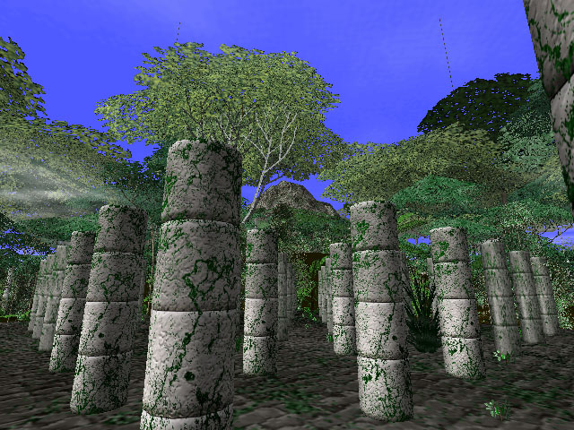
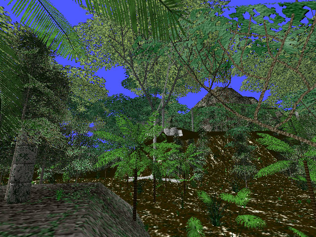
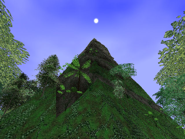
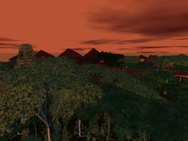
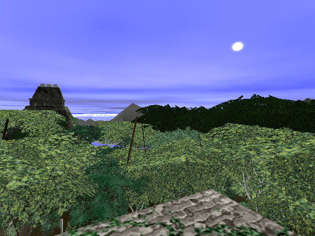
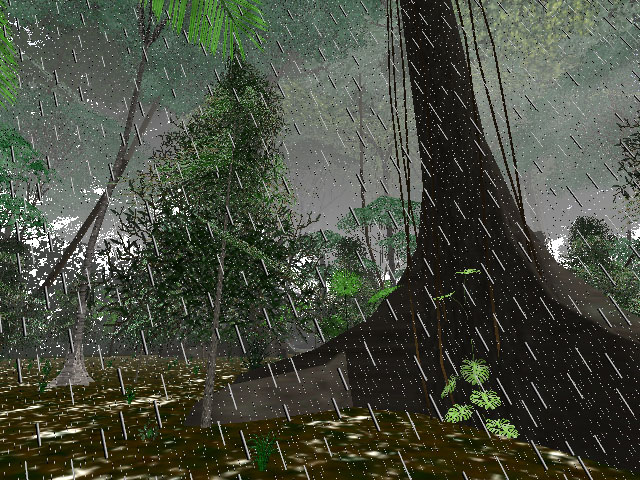
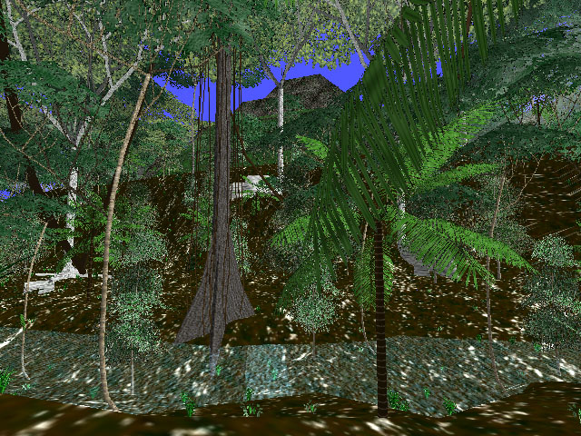
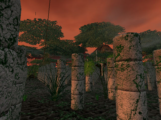
ScreenshotsPlease click on the thumbnails to view larger images. Bear in mind that these are still images. The do not capture any of the following traits: plant sway, cloud drifting, rain falling, day-night cycle, or user-motion. They honestly do not capture the essence of the simulation, but it's the best I could do with reasonable storage requirements. Movies would be quite taxing.
|
||||||||||||||||||||||||||||||||