Electro-etcher/plater/marker
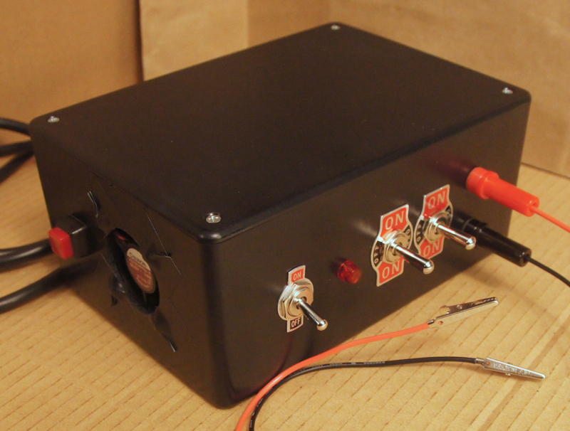
Sections

Introduction

Figured I would give etching/engraving a try. Why not? I considered laser-engraving, hand-engraving (perhaps with a pantograph), acid-etching, and finally electro-etching. Once I started looking to electro-etching, I quickly discovered the related fields of electro-plating and electro-marking and become quite enthralled with all three processes. In addition to being both safer and cheaper than acid-based methods, the newer electrolytic methods are well documented online (although one must sift through an abundance of poor references to find the good ones. Hopefully, my list below will help in that regard).

References

The internet is absolutely soaked in reference material on electro-etching, and to a lesser degree in material on electro-plating and electro-marking. However, by far the most comprehensive and least error-ridden (to the best of my knowledge) resource I have found is Cedric Green's website: http://www.greenart.info/galvetch/contfram.htm.

This project is based on the following designs. As you will notice, this DIYization of electro-etcher/markers has been pioneered by the knife-making community, since they like to electro-mark their creations. I have found that the greater nuance and overall complexity often demanded by etching and plating are disregarded in these references since marking is their primary focus. Nevertheless, I strongly suggest reading them all before embarking on a project of your own:

Electro-etching/plating/marking in general

  1. http://www.greenart.info/galvetch/contfram.htm
  2. http://mordent.com/etch-howto
  3. http://steampunkworkshop.com/electroetch.shtml
  4. http://www.nontoxicprint.com/electroetching.htm
  5. Plus lots of good hits on youtube

At-home electro-etching

  1. http://www.instructables.com/id/How-To-Electro-Etch-a-Solid-Metal-Plaque
  2. Plus lots of good hits on youtube

DIY electro-etcher building instructions

  1. http://www.warnerknives.com/Training.html (although this is the original reference for the next two, it doesn't provide much information online; rather it sells a DVD...which I didn't buy)
  2. http://chriscrawfordknives.com/#/electro-etching-unit/4535265119 (based on #1, above)
  3. http://www.logiudicecustomknives.com/knifeshop/etcher/index.shtml (based on #2, above)
  4. Plus lots of good hits on youtube

Design & Circuit Diagram

My design differs from those in the references in the following ways:

  1. It attempts to be a comprehensive system, providing all three possible modes: etching, plating, and marking (although for reasons stated below I primarily intend to use it for marking). Some of the others don't focus on this distinction too specifically, although to be honest, they should all be applicable to the various modes of use if configured and used properly. Etching requires DC, marking requires AC, and plating simply requires hooking the DC mode up in reverse w.r.t. which end (anode or cathode) is the workpiece and which is sacrificial.
  2. I wanted to offer some voltage control. My design is quite minimal in this regard, but does offer a two-level switch between 6V and 12V (or if you substitute a 12-0-12 transformer into the design you can make a system that toggles between 12V and 24V). Frankly, this degree of control is probably insufficient. My goal is to achieve extremely low voltages toward the goal of increasing the resolution (fine detail) of an etch. This goal could be achieved by the further addition of a DC potentiometer (adjustable resistor) or perhaps an AC dimmer (if applied on the primary side of the transfomer, although I'm not sure if these transformers require 120VAC input).
  3. The secondary circuit is grounded via one of the transformer end-taps. I can't claim credit for the ingenuity of this design; it was recommended during discussion in an electronics forum.
  4. I added a fan to my design, although I doubt it is necessary. The fan is a 12V DC fan, which means that of the four possible modes of operation (AD/DC and 6V/12V) the fan only runs well in one mode. Given its decreased utility in the other modes (lower speed or total inability to run depending on the mode), and given the unfortunate fact that the fan I used had a bad shake which, while not bothersome in isoloation, was amplified by the enclosure as a soundbox into a really annoying buzz, I then also added the complexity of an on/off switch to the fan.
  5. Some of the references reverse the conventional red/black, positive/negative assignment. I chose to wire it the usual way to maximize clarity and minimize mistakes.

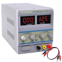
Future work would include the addition of a potentiometer to the DC circuit to gain better control over the voltage and the addition of a voltmeter and ammeter to enable monitoring of the power characterics. One could also add a smoother capacitor to the DC circuit. I didn't bother because it isn't really necessary for electro-etching and plating.

It should be noted that I don't really intend to use this device for etching or plating, only for marking. I purchased a really nice 30V DC power supply for etching and plating (shown below). It provides voltage control to ~1/10th volt precision starting from 0V as well as offering control over the max permissable current flow (i.e., amps). It also provides digital voltage and amperage displays to sub-volt precision. However, it doesn't provide AC power. In fact, it's practically impossible to buy an AC power supply since virtually no useful devices run on AC power. I built this device almost exclusively to fill my need for AC power toward the purpose of electro-marking....oh, and it was gobs of fun too.
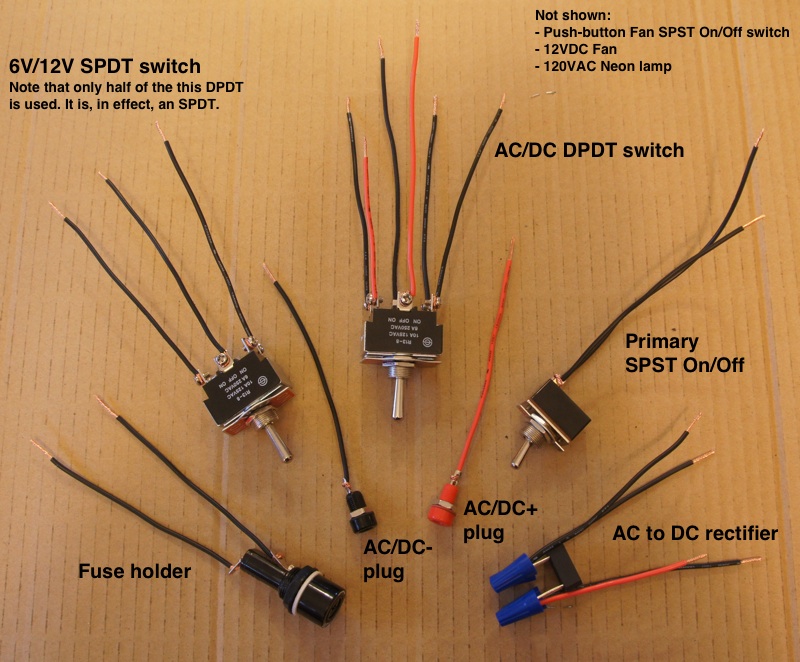
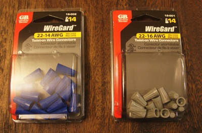
Variable voltage Current-limiting DC Power Supply

This is the DC power supply I intend to use for most of my etching and plating. I got it off ebay for about $60 (comparable to the cost of building the unit described on this page). The device I built, as described on this page, will be used primarily for electro-marking, which requires AC current and less precise control over voltage than etching.
Circuit Diagram
Click to enlarge

Parts

Radio Shack part numbers are included in the parts photo below. I traded out the 24V (12-0-12) transformer from some of the references for a 12V (6-0-6) since I see little need for excessively high voltages (I'll never need 24V anyway) while simultaneously desiring rather low voltages (it'll be nice to get down to 6V, although 0V to 3V might be even more useful, I'm not sure yet (thus I purchased the DC power supply described above)). Both transformers provide a 12V option of course.

Note that while I purchased two DPDTs, one acts essentially as an SPDT. Radio Shack didn't have the SPDT in stock, and besides, the DPDT looks nicer; it has a really nice label on the front. Note that I used a slightly different fuse holder than the references. This was originally a mistake; I grabbed the wrong part at Radio Shack. I was about to return it since it's more expensive but then I read the reviews online and people said the intended fuse holder breaks a lot anyway, so I just kept the one I bought. Rather than purchase a power cable, I went to a thrift store with the intention of buying an entire electrical gizmo for less than the price of a new cable and simply cutting the cable off. As it turned out, I found bare cables at the thrift store anyway. Even better. If you do this, make sure you get a three-prong grounded cable, and make sure it's a beefy 10A cable, just to be safe.

In summary, I got most of the parts new from Radio Shack, the wire connectors from a local general store (since Radio Shack was staggerly deficient in such items), and as stated, I avoided the $11.00 Radio Shack power cable in favor of a $2.00 thrift store alternative. The fan, push-button switch, and alligator clips were liberated from my electronics odds-n-ends box, the remnants of earlier electronics projects. Final cost including tax was about $70. Pretty silly considering the DC power supply was $60 with all its fine-tuned controls and digital displays...but I need AC for electro-marking!

Click to enlarge
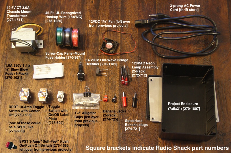
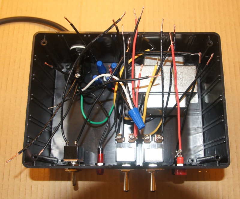
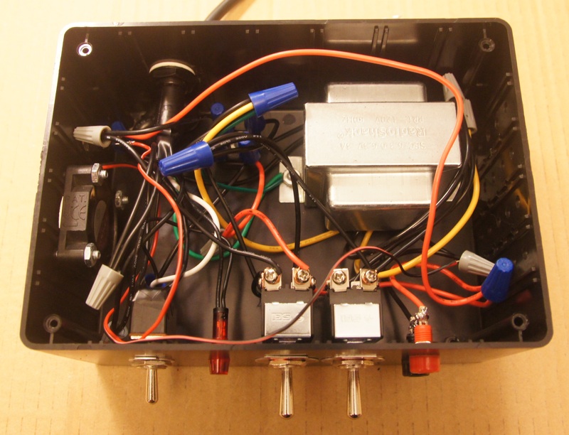
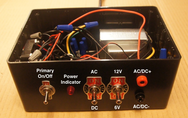
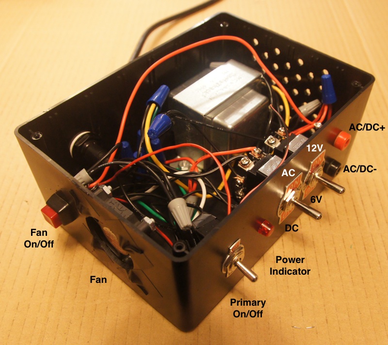
Construction

Preparing the components
Click to enlarge

Nothing too complicated to see here. You'll notice that the AC/DC DPDT is color-coded: the red 'throw' wire corresponds to DC+ while all other lines correspond to DC- or AC (the red 'pole' wire is, admittedly, ambiguous since it can provide either DC+ or AC power). As described above, the other DPDT is only wired on one side; it is essentially an SPDT. Also it's important to note that the 120VAC connections, while exposed in this photo, will be insulated with electrical tape later in the build (because death isn't fun).
Inserting the components in the enclosure
Click to enlarge

This photo shows most of the components inserted into the box with their wires flailing about. The only things missing are the fan and the fan switch.
Connecting the component wires
Click to enlarge

Here it is with all the wires connected. The fan and fan on/off switch are also incorporated at this point. Finally, as stated above, note that the 120VAC connections are inulsated with electrical tape (both connections on the fuse holder and both connections on the primary on/off switch).
The front panel
Click to enlarge

I haven't labeled the switch positions yet, so I did it with text overlays on the photo, but obviously I'll do that pretty soon.
3/4 view showing the fan and fan-on/off switch
Click to enlarge

This shot shows the fan and the fan on/off switch. Seems pretty straight-forward.
Closed up and ready to go (still needs switch sticker labels)
Click to enlarge

Video demonstrating voltage tests

Results

Please click here to view etching experimental results.